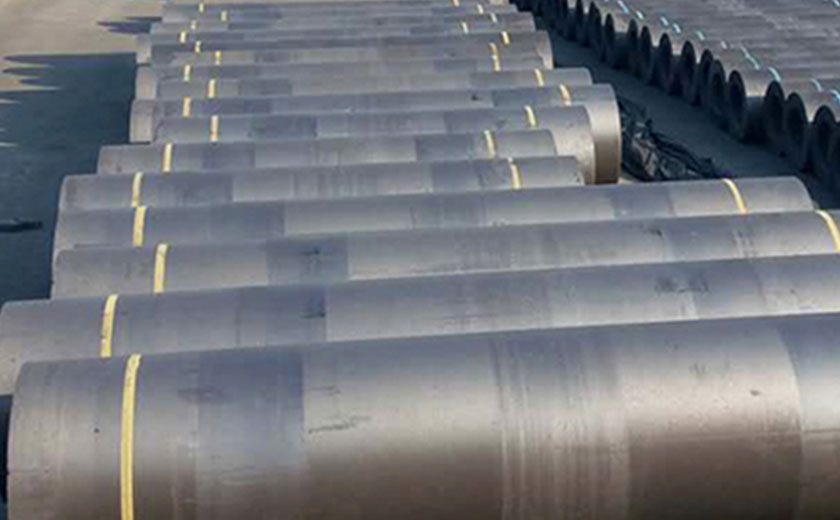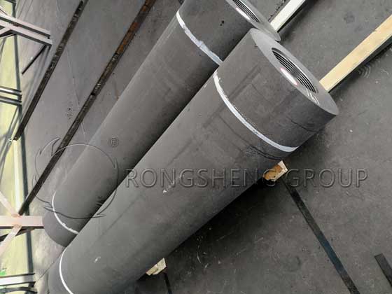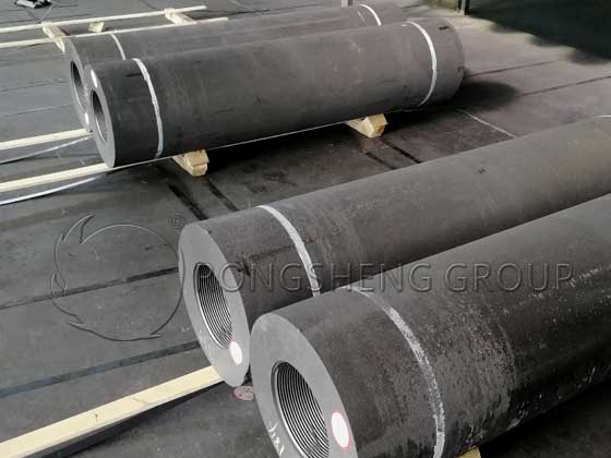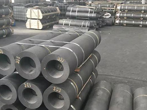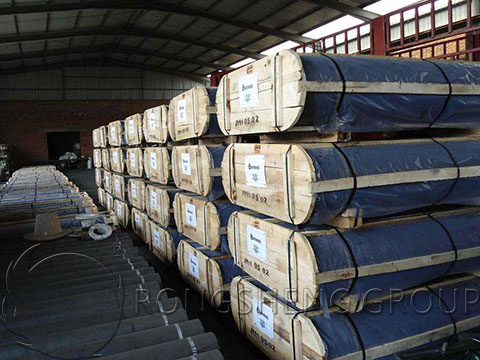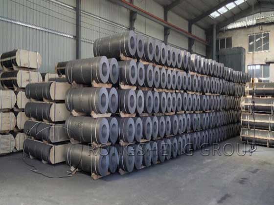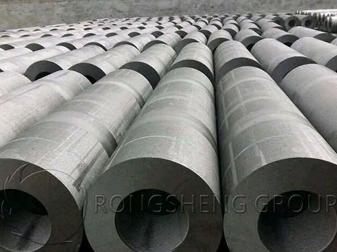
Rongsheng HP and UHP Graphite Electrodes are for sale. Graphite electrodes play a crucial role in numerous high-temperature industrial processes, particularly in electric arc furnaces (EAFs) and ladle furnaces (LFs). As one of the leading providers of high-performance refractory products, Rongsheng Graphite Electrode Manufacturer supplies robust and durable graphite electrodes tailored for industrial applications requiring high conductivity, superior heat tolerance, and exceptional mechanical strength. This post delves into the unique features and benefits of our HP (High Power) and UHP (Ultra High Power) graphite electrodes, with a focus on those measuring Dia 200 x 1800mm and equipped with nipples for efficient connectivity and enhanced performance.
Why HP and UHP Graphite Electrodes?
The choice between HP and UHP graphite electrodes depends on the specific requirements of the industrial application. HP graphite electrodes are suitable for moderate electrical loads and stable furnace conditions, while UHP graphite electrodes are engineered to endure intense electrical currents and higher temperatures.
For high-demand environments like electric arc furnaces used in steelmaking, UHP electrodes are the preferred choice due to their ability to withstand high energy output and rapid thermal cycling. HP electrodes, although suitable for high power needs, are generally deployed in furnaces where energy demands and temperature thresholds are slightly lower. Understanding these distinctions enables industries to select the appropriate electrode grade for their specific application.
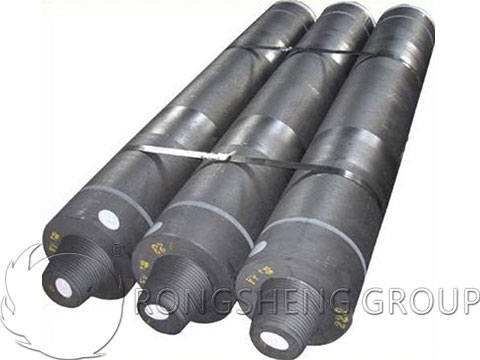
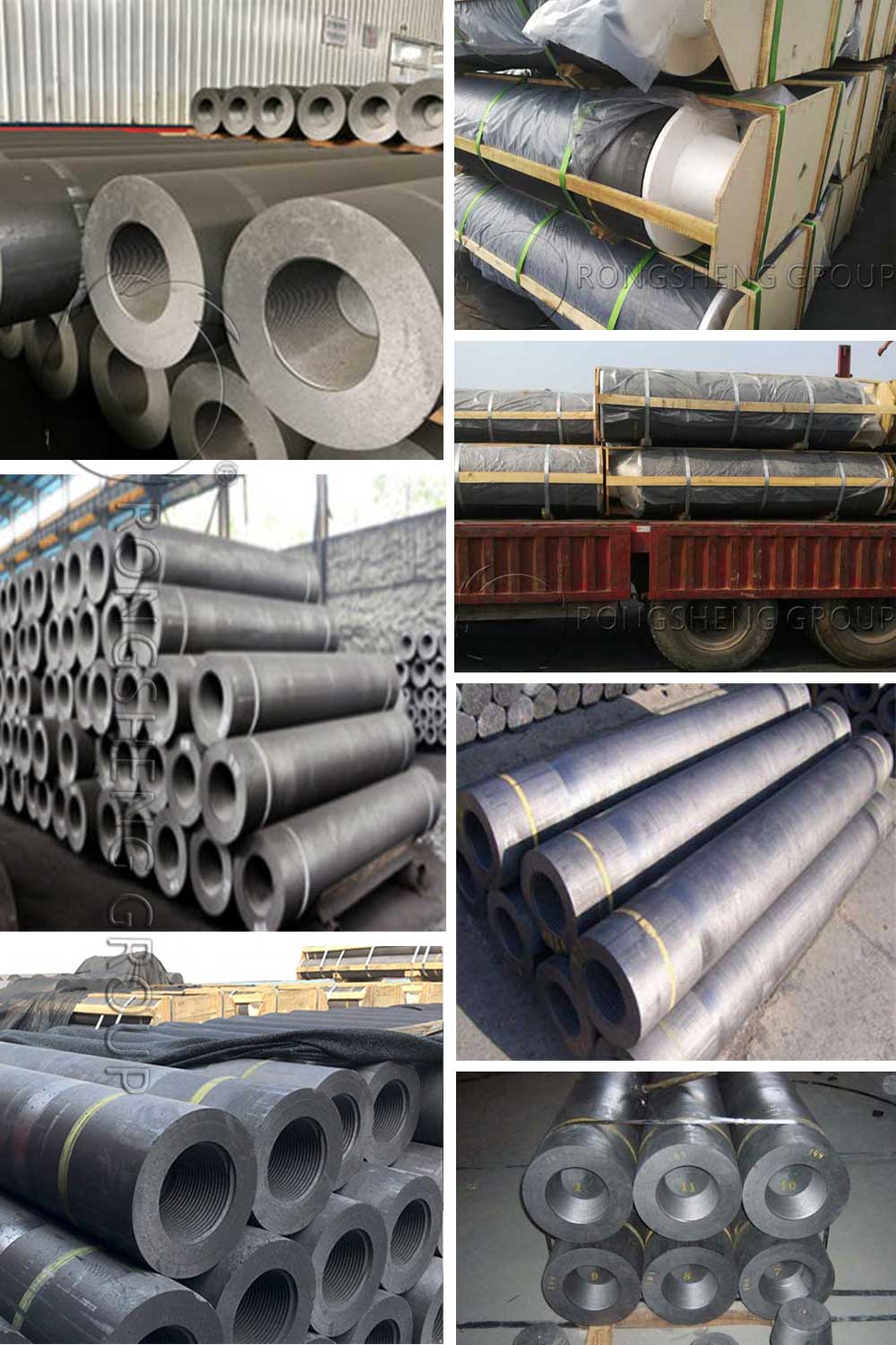
Key Features of Rongsheng Graphite Electrodes with Nipple Dia 200 x 1800mm HP Grade and UHP Grade
High Density and Purity
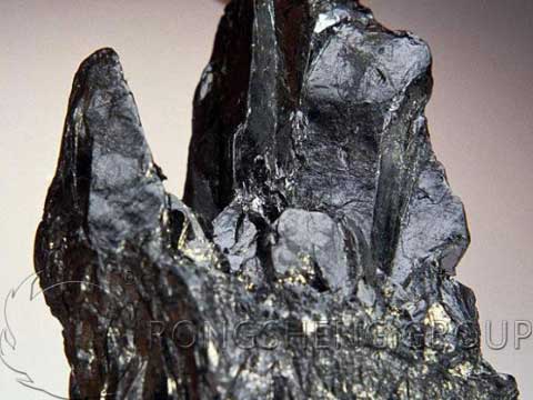
Our graphite electrodes are manufactured from high-quality, low-ash petroleum coke, resulting in an electrode with superior density and purity. The high purity enhances thermal and electrical conductivity while reducing carbon contamination in sensitive industrial processes.
Optimized Mechanical Strength
Mechanical strength is a crucial factor for electrodes exposed to high-energy environments. The specific manufacturing processes of our HP and UHP graphite electrodes ensure that they maintain structural integrity even under intense thermal cycling, reducing the risk of fractures or breakage.
Excellent Electrical Conductivity
HP and UHP graphite electrodes exhibit excellent electrical conductivity, which is essential for reducing energy loss in high-current applications. Our UHP-grade electrodes, in particular, are designed for maximum current-carrying capacity, making them ideal for use in high-power EAFs.
Extended Service Life
The durable composition and robust performance of Rongsheng electrodes lead to longer operational lifespans compared to standard electrodes. This reduces the frequency of electrode replacement, thereby minimizing production downtime and cost.
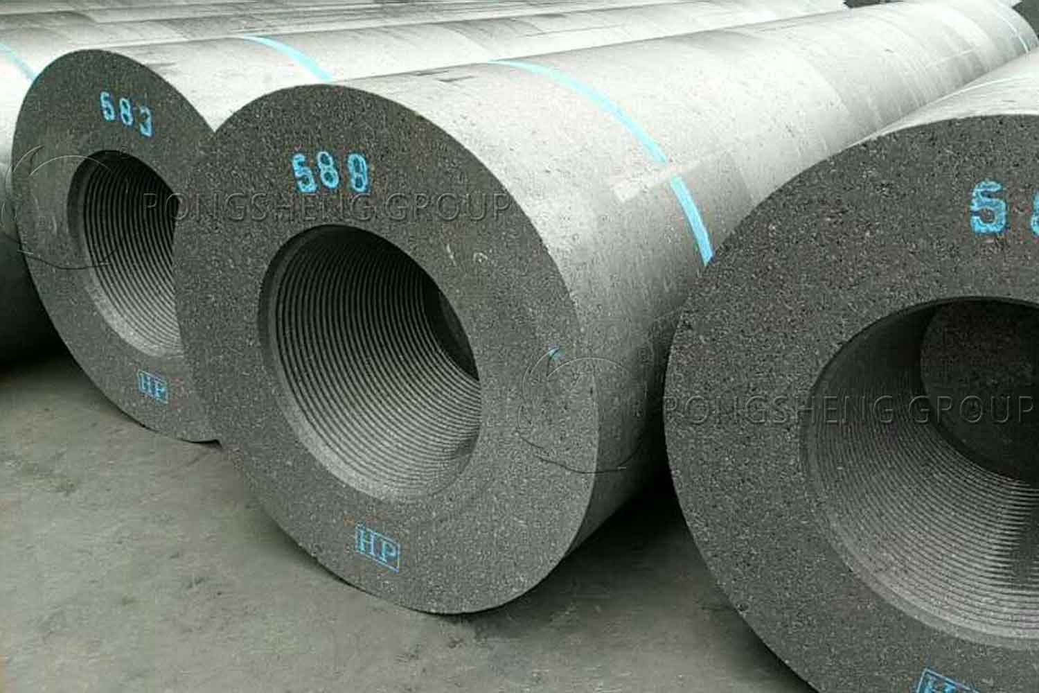
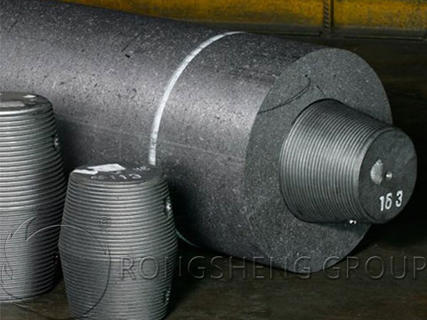
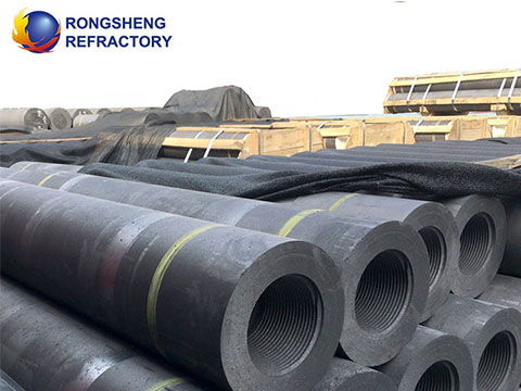
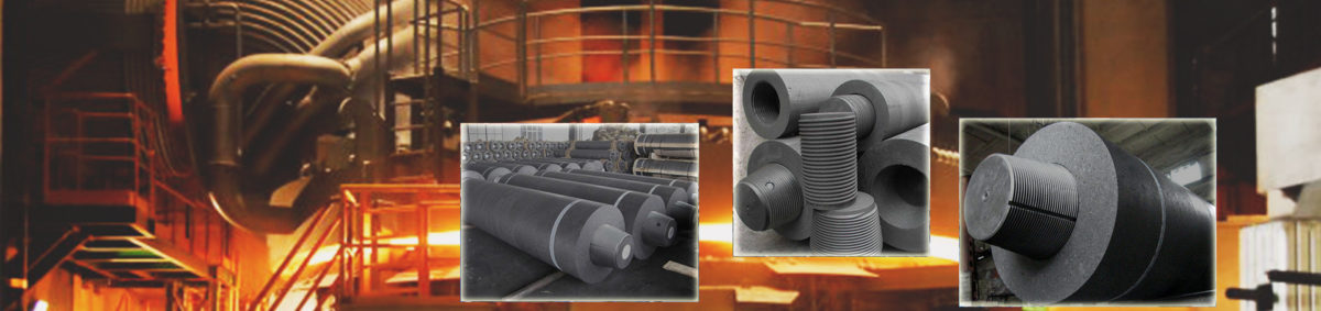
Nipple Joint Technology for Improved Connectivity
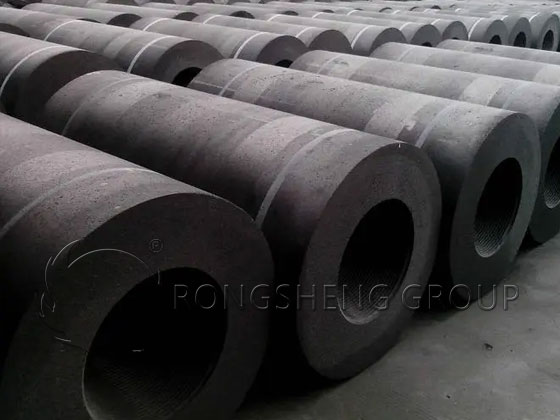
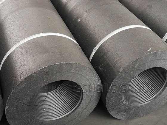
Our Dia 200 x 1800mm graphite electrodes come with nipples designed to provide a stable, conductive connection between electrode segments. These nipples are precisely engineered to maintain seamless current flow, reducing energy loss and promoting efficient operation in electric arc furnaces.

Applications of HP and UHP Graphite Electrodes in High-Temperature Industries
Steel Manufacturing
Steelmaking is one of the primary applications for graphite electrodes. In electric arc furnaces, UHP graphite electrodes are used to melt steel scrap. The superior electrical conductivity and temperature tolerance of our UHP electrodes make them ideal for this demanding application.
Foundries and Smelting Industries
HP and UHP electrodes are also used in foundries for the melting of ferrous and non-ferrous metals. The high-energy demands of these processes require electrodes that can efficiently handle electrical loads and thermal stress, making HP and UHP electrodes suitable choices.
Chemical Industries
In chemical manufacturing, graphite electrodes are employed in processes like the production of phosphorus, silicon metal, and other high-temperature applications. The stability and low impurity levels of our graphite electrodes ensure that they are compatible with such applications, providing reliable performance.
Electric Arc Furnaces (EAFs) and Ladle Furnaces (LFs)
EAFs and LFs are critical in recycling scrap metal, an increasingly important process in today’s sustainable production models. Rongsheng’s UHP graphite electrodes can endure the high currents and prolonged exposure to high temperatures needed in these furnaces, improving operational efficiency and production rates.

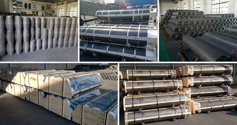
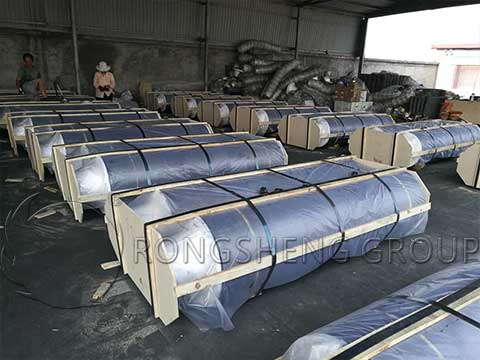
Manufacturing Process: Quality Assurance and Customization
Rongsheng ensures the highest standards in electrode production. Our manufacturing process involves a series of carefully controlled steps, from raw material selection to machining and inspection, ensuring that each electrode meets rigorous quality standards.
Raw Material Selection
Only high-quality, low-sulfur petroleum coke and needle coke are used, optimizing the electrode’s performance under high temperatures and electrical loads.
Baking and Graphitization
The baking and graphitization phases are carried out in controlled environments to enhance the electrodes’ density, electrical conductivity, and oxidation resistance. UHP electrodes undergo additional treatments to ensure that they can handle higher power demands without compromising structural integrity.
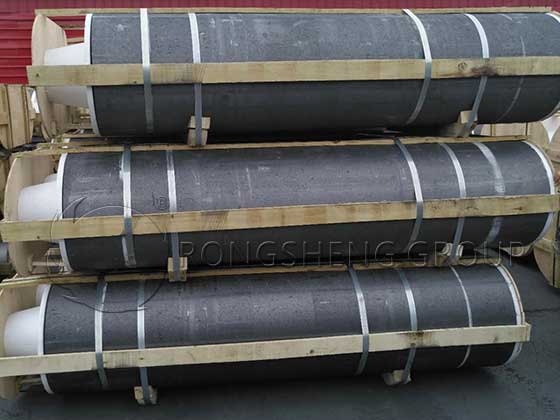
Precision Machining and Testing
Our electrodes and nipples are machined to precise specifications, guaranteeing reliable connections and minimal electrical resistance. Rigorous testing procedures assess each electrode’s quality, durability, and performance.
Environmental Benefits and Sustainability
Graphite electrodes offer several sustainability advantages, especially in steel recycling and metal smelting industries. By efficiently converting electrical energy into heat, these electrodes support the recycling of scrap metal, reducing reliance on virgin resources and lowering industrial emissions. Rongsheng is committed to producing environmentally responsible graphite electrodes, ensuring that our products contribute to sustainable production methods.
Rongsheng’s HP and UHP Graphite Electrodes
Rongsheng’s HP and UHP graphite electrodes, specifically our Dia 200 x 1800mm models with nipple technology, are engineered to meet the high-performance demands of electric arc furnaces, steel manufacturing, and other industrial applications. The exceptional durability, electrical conductivity, and thermal resilience of our electrodes make them a trusted choice for industries worldwide. Whether you need HP-grade electrodes for moderate electrical loads or UHP-grade electrodes for more extreme conditions, Rongsheng is dedicated to delivering products that support operational efficiency, quality, and sustainability.
Contact Rongsheng Now
Explore the benefits of Rongsheng’s HP and UHP graphite electrodes and discover how our Dia 200 x 1800mm electrodes can enhance your production process. Contact the Rongsheng team to learn more about our product offerings and customization options that cater to your specific industrial needs.