Rongsheng – A Trusted Global Graphite Electrode Supplier. As steelmaking, metallurgy, and high-temperature industries evolve, demand grows for durable, energy-efficient, and stable electrode materials. At the core of these processes lies the graphite electrode, a material capable of conducting intense electrical current and sustaining temperatures over 3000°C.
Rongsheng, an internationally recognized graphite electrode supplier, provides a complete line of graphite electrodes and precision-engineered graphite electrode nipples to meet diverse industrial needs. The company’s expertise ensures reliable performance, minimal energy loss, and extended electrode life, allowing manufacturers to achieve consistent production efficiency.
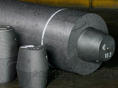
Graphite Electrodes – Powering the Heart of High-Temperature Processes
Graphite electrodes act as the main conductive medium in electric arc furnaces (EAFs) and ladle furnaces (LFs). Their performance determines the melting speed, energy consumption, and cost-efficiency of industrial operations.
Rongsheng manufactures graphite electrodes across multiple power grades — from Regular Power (RP) to High Power (HP) and Ultra High Power (UHP). Each grade is tailored to specific furnace demands:
-
- RP Graphite Electrodes: Suitable for standard steelmaking and refining at regular current densities.
- HP Graphite Electrodes: Designed for higher current loads and faster melting cycles.
- UHP Graphite Electrodes: Engineered for heavy-duty, high-efficiency furnaces operating at maximum power input.
These electrodes are valued for their excellent conductivity, mechanical strength, and oxidation resistance — qualities that keep production running smoothly and efficiently.
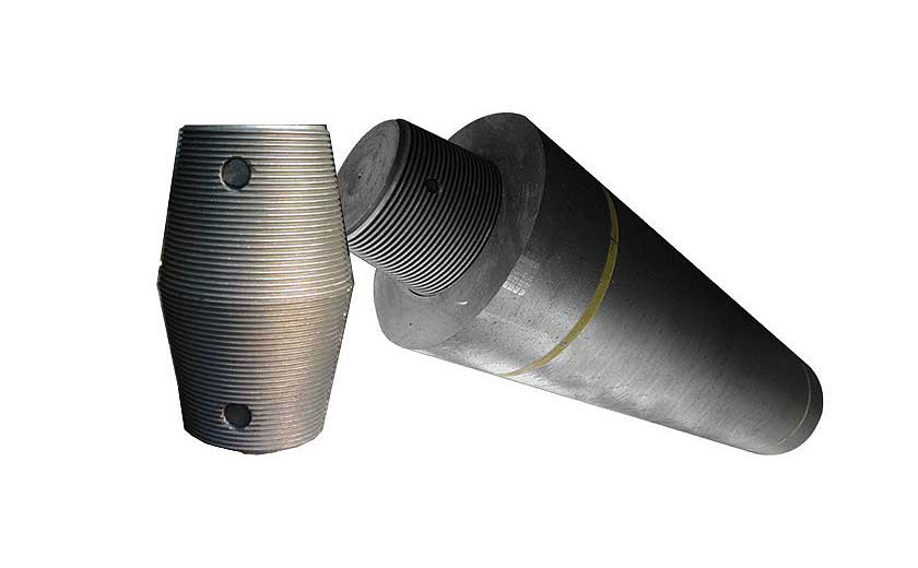
Precision-Engineered Graphite Electrode Nipples
The graphite electrode nipple is a crucial but often overlooked component in furnace operations. It connects individual electrode sections, ensuring electrical continuity and mechanical strength throughout the column. Poor nipple quality can lead to joint failure, arc instability, and increased electrode loss — all of which raise production costs.
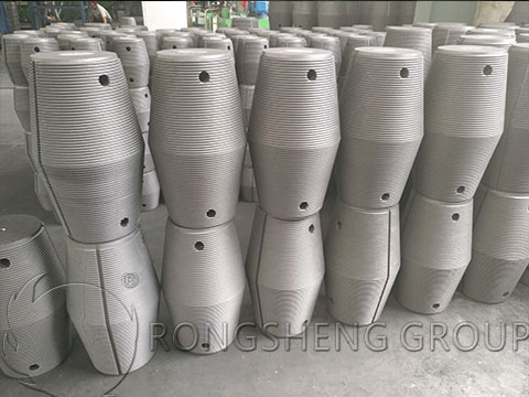
Rongsheng designs and produces nipples with tight dimensional tolerances and fine surface finishes, guaranteeing a perfect thread match with the electrode body. Each nipple undergoes rigorous machining and inspection to ensure:
-
- Low Electrical Resistance: Minimizing power loss at the joint.
- Strong Mechanical Bond: Preventing disconnection under furnace vibration and high thermal stress.
- Thermal Compatibility: Ensuring the nipple and electrode expand uniformly during heating cycles.
By providing matched electrodes and nipples from the same production line, Rongsheng ensures seamless connections and enhanced operational reliability.
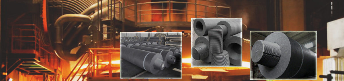
Applications – Graphite Electrodes and Nipples in Modern Industry
Rongsheng’s electrodes and nipples are used across industries that rely on controlled high-temperature environments. Their performance directly influences product quality, furnace efficiency, and operating cost.
1. Steelmaking in Electric Arc Furnaces (EAF)
In EAFs, graphite electrodes carry the electrical current that generates the arc required to melt scrap steel. The intense heat — often above 3000°C — is sustained through the electrode tips.
-
- Rongsheng’s UHP graphite electrodes provide rapid melting with reduced power loss.
- Graphite electrode nipples maintain joint stability even under continuous thermal cycling, preventing premature failure.
2. Refining in Ladle Furnaces (LF)
During secondary refining, electrodes help maintain molten steel temperature and control chemical composition.
-
- Rongsheng’s HP and RP electrodes ensure precise heating and uniform metallurgical results.
- Precision nipples maintain uninterrupted current flow throughout the process.
3. Alloy and Non-Ferrous Metal Production
In silicon, nickel, and copper processing, graphite electrodes provide steady electrical energy for smelting and refining.
-
- RP graphite electrodes are suitable for smaller furnaces and continuous operations.
- Matched nipples help maintain uniform conductivity during extended use.
4. Chemical and Material Manufacturing
Graphite electrodes also serve as heating sources in furnaces used to produce high-purity materials such as corundum, silicon carbide, and quartz glass. The electrodes’ stability and resistance to oxidation make them ideal for long production runs.
Manufacturing Excellence – The Rongsheng Advantage
As a seasoned graphite electrode supplier, Rongsheng manages every stage of production with precision. Its manufacturing process combines advanced technology, strict quality control, and decades of industrial experience.
-
-
Raw Material Selection: Premium needle coke and binder pitch ensure high conductivity and structural strength.
-
Forming: Uniform extrusion under controlled pressure for consistent density.
-
Baking and Impregnation: Multi-stage baking and impregnation enhance durability and reduce porosity.
-
Graphitization: Transformation at nearly 3000°C to achieve crystalline structure and improved electrical properties.
-
Machining: Electrodes and nipples are CNC-machined for perfect fit and precise threading.
-
Inspection: Each batch is tested for density, resistivity, and mechanical strength before packaging.
-
By integrating these steps, Rongsheng delivers graphite electrodes with high product qualification rates and a reputation for reliability.
Why Rongsheng is a Preferred Graphite Electrode Supplier
Rongsheng’s success lies not only in product quality but also in customer-centered service and global reach. As a trusted graphite electrode supplier, the company offers:
-
- Customized Sizes: From 100 mm to 700 mm diameters and lengths up to 2700 mm.
- Matched Sets: Electrodes and nipples machined together for optimal performance.
- Competitive Pricing: Factory-direct supply reduces procurement costs for clients.
- Global Export Network: Trusted by steelmakers and furnace operators in over 120 countries.
- Technical Support: Expert consultation on electrode selection, installation, and performance optimization.
Each electrode shipment comes with full documentation and traceability, providing assurance of quality and consistency.
Customer Case – Improving Efficiency Through Better Connections
A European steel producer replaced mismatched third-party electrodes and connectors with Rongsheng’s graphite electrodes and precision nipples. Within months, the plant recorded:
-
- A 10% reduction in electrode consumption.
- Fewer power interruptions caused by joint failure.
- More stable arc performance during continuous steelmaking cycles.
This improvement translated directly into lower operating costs and higher production consistency — proof of the impact that high-quality electrodes and nipples can deliver.
Sustainability and Future Commitment
Rongsheng continues to innovate in energy efficiency and sustainability. The company invests in environmentally friendly production technology, minimizing emissions during graphitization and reducing waste in machining processes.
By combining product excellence with responsible manufacturing, Rongsheng helps clients meet both performance and sustainability goals — a reflection of its long-term vision as a global graphite electrode supplier.
Conclusion
In every electric arc furnace, success depends on the strength of the connection — between energy, material, and precision engineering. Rongsheng’s graphite electrodes and graphite electrode nipples form that vital connection.
As a professional graphite electrode supplier, Rongsheng continues to provide reliable, efficient, and cost-effective products to steelmakers, metallurgical companies, and high-temperature industries around the world.
📩 Contact Rongsheng today for consultation and quotation.
🌐 Visit the official website to learn more about the company’s full range of graphite electrodes and nipples.